The aerodynamic loads on a wind turbine rotor are often calculated using Blade Element – Momentum theory (BEM). As part of my PhD thesis (Lupton 2015) I implemented the BEM calculations in Python, and I’ve now tidied this up as an open-source Python package bemused that I’ll introduce here.
import bemused
bemused.__version__
## '0.2.0'The BEM calculations break the rotor up into discrete annuli (a series of concentric rings) and calculate the loads on each one separately. As an example, let’s use the blade parameters from the NREL 5MW wind turbine (Jonkman et al. 2009). The relevant data is stored in a YAML file NREL5MW_simpblade.yaml that can be loaded by bemused:
blade_definition = bemused.Blade.from_yaml('NREL5MW_simpblade.yaml')The blade parameters used by the BEM model are the chord, thickness and twist at a series of “blade stations” spaced along the length of the blade. Let’s plot those:
fig, ax = plt.subplots(3, 1, sharex=True)
fig.subplots_adjust(bottom=0.15, top=0.99, left=0.15)

def plot_blade(a, y, label):
  a.plot(blade_definition.x, y, '.-', markersize=3, linewidth=1)
  a.set_ylabel(label)
  a.set_ylim(bottom=0)
  remove_top_right_spines(a)

plot_blade(ax[0], blade_definition.chord, 'Chord [m]')
plot_blade(ax[1], blade_definition.thickness, 'Thickness [%]')
plot_blade(ax[2], blade_definition.twist * 180/np.pi, 'Twist [deg]')
ax[-1].set_xlabel('Distance along blade [m]')
fig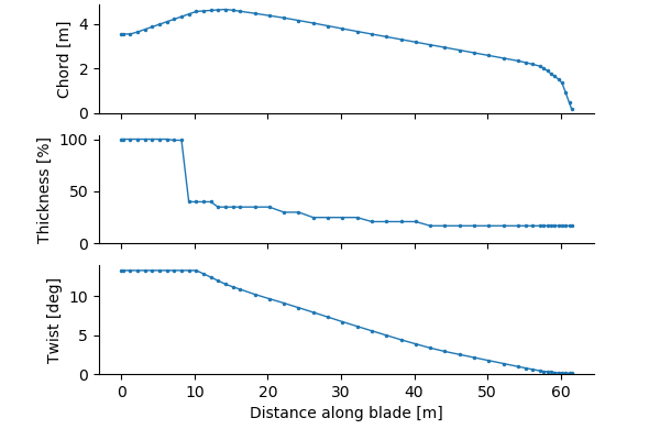
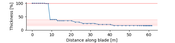
At each of these blade stations, we need to know the aerodynamic coefficients that describe the lift and drag forces created by the aerofoil. We have saved the tables of coefficients for several reference aerofoils along the blade, which are interpolated based on the blade thickness to get the actual coefficients at each station.
aerofoil_database_filename = 'oc3_aerofoils.npz'
aerofoil_database = bemused.AerofoilDatabase(aerofoil_database_filename)
As it happens, in this database we have the coefficients defined for every thickness along the blade, so no interpolation is necessary:
For example, here are the lift and drag coefficients for the thinnest aerofoil profile (17%):
# Details of plotting code not included here for clarity...
aerofoil = aerofoil_database.for_thickness(thicknesses[0])
plot_aerofoil_coefficients(alpha=aerofoil_database.alpha,
                           CL=aerofoil[:, 0],
                           CD=aerofoil[:, 1])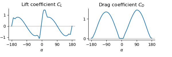
That’s all the information we need about the blades — let’s use the BEM model to calculate the thrust and torque on the rotor! We have a little more setup to do to assemble the blades into a rotor:
# The blades are attached to a hub, which joins them onto the main shaft,
# so the root (inboard end) of the blade is not at the centre of the rotor.
# The radius of the root is called the "root length". Here the hub diameter
# is 3m, so the root length is half of that.
root_length = 1.5

# Let's have a normal three-bladed rotor.
number_of_blades = 3

model = bemused.BEMModel(
  blade_definition, root_length, number_of_blades, aerofoil_database)
The loads in the BEM model depend on the rotor speed, the blade pitch angle, and the wind speed. Let’s calculate the thrust curve and power curve of the rotor by doing the BEM calculations for a range of wind speeds. To do this properly we would need to calculate the appropriate rotor speed and pitch angle for each wind speed, but for now let’s just assume they are fixed:
rotor_speed = 9.45 * (np.pi/30)  # 9.45rpm converted to rad/s
pitch_angle = 0
wind_speeds = np.arange(4, 9, 0.5)
air_density = 1.225  # kg/m3

forces = np.zeros((len(wind_speeds), len(blade_definition.x), 2))

for i in range(len(wind_speeds)):
  # First solve for the induction factors at this wind speed...
  factors = model.solve(wind_speeds[i], rotor_speed, pitch_angle)

  # ...then use them to calculate the forces
  forces[i] = model.forces(wind_speeds[i], rotor_speed, pitch_angle,
                           air_density, factors)
We now have the distribution of in-plane and out-of-plane forces along the blade. For example, we can plot forces[1, :, 0] to show the thrust distribution along the blade at the second wind speed (4.5 m/s):
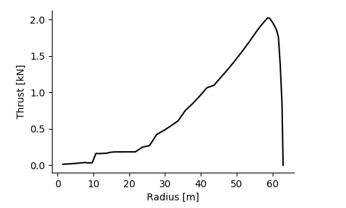
The total rotor thrust is the sum of all the out-of-plane forces on the annuli:
thrust = number_of_blades * np.trapz(forces[:, :, 0], model.radii, axis=1)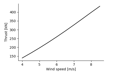
And the torque is similarly calculated as the sum of the moments of the in-plane forces:
torque = (-number_of_blades *
          np.trapz(model.radii * forces[:, :, 1], model.radii, axis=1))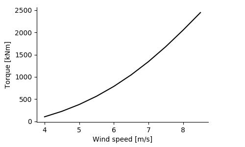
Find out more
For more information on bemused see the API documentation and the code on GitHub.
References
Jonkman, J, S Butterfield, W Musial, and G Scott. 2009. “Definition of a 5-MW Reference Wind Turbine for Offshore System Development.” NREL/TP-500-38060. National Renewable Energy Laboratory. https://www.nrel.gov/docs/fy09osti/38060.pdf.
Lupton, Richard C. 2015. “Frequency-Domain Modelling of Floating Wind Turbines.” PhD thesis, University of Cambridge. https://doi.org/10.17863/CAM.14119.